What Is This?
The USB2USB adapter lets you plug any supported USB controller into one side and get a standard USB gamepad out the other. Think of it as a universal controller translator and remapper.
Why would you want this?
- Use your favorite controller everywhere — Plug a DualSense into a PC that only expects Xbox, or a Switch Pro Controller into a PS3
- Choose your output — SInput (default), XInput, PS3, PS4, Switch, PS Classic, Xbox, Keyboard/Mouse, GC adapter, and more. The selected mode is saved to flash.
- Remap buttons via config.joypad.ai — no software to install
- Works on real Xbox 360 consoles — XInput mode authenticates via XSM3
How It Works
A USB-to-USB translator needs two USB roles at the same time:
- A device port that outputs a standard USB gamepad to your PC or console. This is the board's native USB port (also used for flashing).
- A host port that reads your controller. There are two ways to get this host port, which is what the two build paths below are about.
The easiest path uses a board with a built-in USB-A host port — no wiring at all. The advanced path uses PIO-USB, a software USB host implemented on the RP2040/RP2350's PIO peripheral, where you wire a USB-A port to specific GPIO pins.
PIO-USB limits: Full-Speed (12 Mbps) only, a single device, and no USB hubs — connect your controller directly.
Choose Your Board
Option A: Built-In USB-A Host (No Soldering — Recommended)
These boards already have a USB-A host port, so your controller plugs right in. The native USB port connects to your PC (or console) as the output. Zero wiring.
- Adafruit Feather RP2040 with USB Type-A Host (product #5723)
- Waveshare RP2350A-USB-A
Best for: First-timers, and anyone who just wants it to work. Difficulty: Easy.
Option B: PIO-USB Wiring (Advanced)
Wire a USB-A port to your board's GPIO pins so controllers can plug in. Four wires, a bit of soldering. Works on the popular Raspberry Pi Pico family and the Waveshare RP2040-Zero.
Best for: Tinkerers, budget builds, or a Pico you already have. Difficulty: Medium.
Parts List
Option A — Built-In USB-A Host (No Soldering)
| Part | Notes |
|---|---|
| Adafruit Feather RP2040 USB Host (#5723) or Waveshare RP2350A-USB-A | Board with a built-in USB-A host port |
| USB data cable | Must be data-capable (matches your board's native USB connector) |
That's it. Seriously.
Option B — PIO-USB Wiring
| Part | Notes |
|---|---|
| Raspberry Pi Pico / Pico W / Pico 2 W, or Waveshare RP2040-Zero | The controller board |
| USB-A female breakout board, or a cut USB-A extension cable | Provides the host port (4 wires: D+, D-, 5V, GND) |
| USB data cable | Must be a data cable, matching your board's native USB connector |
| Jumper/hookup wire | Only if using a breakout board — a cut USB-A cable already has its four wires |
| Soldering iron + solder | If your parts aren't solderless |
Note: Confirm current prices with each vendor before ordering — parts pricing changes over time.
Wiring (Option B — PIO-USB Only)
If you're using a built-in USB-A host board (Option A), skip this section entirely. The USB-A host port is already wired.
You're connecting a USB-A female breakout (or a cut USB-A extension cable) to your board so controllers can plug in — just four wires: D+, D-, 5V (VBUS), and GND.
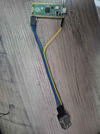
USB-A Connector Pinout
  ┌───────────────────┐
  │ 1   2   3   4     │
  └───────────────────┘
   VBUS  D-  D+  GND
   (5V)
| USB-A Pin | Signal | Color (typical) |
|---|---|---|
| 1 | VBUS (+5V) | Red |
| 2 | D- | White |
| 3 | D+ | Green |
| 4 | GND | Black |
Raspberry Pi Pico / Pico W / Pico 2 W
D+ and D- must be on consecutive GPIOs (D- is always D+ + 1).
| Board Pin | USB-A Pin | Signal |
|---|---|---|
| GPIO 16 | 3 | D+ (green) |
| GPIO 17 | 2 | D- (white) |
| VBUS | 1 | 5V (red) |
| GND | 4 | GND (black) |
Waveshare RP2040-Zero
| Board Pin | USB-A Pin | Signal |
|---|---|---|
| GPIO 10 | 3 | D+ (green) |
| GPIO 11 | 2 | D- (white) |
| 5V | 1 | 5V (red) |
| GND | 4 | GND (black) |
Note: The Waveshare RP2350A-USB-A also uses PIO-USB internally (D+ = GPIO 12, D- = GPIO 13), but it already has the USB-A host port on the board, so it belongs in the no-solder Option A above — no wiring needed.
Wiring Tips
- Double-check D+ and D- — swapping them is the #1 mistake and everything will silently fail
- Keep wires short (under ~15 cm / 6 inches) — USB signal quality degrades with length
- A breakout board with labeled pins is much easier than cutting a USB cable
- No USB hubs — connect your controller directly (PIO-USB doesn't support hubs)
Flash the Firmware
Step 1: Download the UF2
Go to github.com/joypad-ai/joypad-os/releases and download the right file for your board:
| Board | Firmware File |
|---|---|
| Feather RP2040 USB Host | joypad_*_usb2usb_feather_rp2040_usb_host.uf2 |
| Waveshare RP2350A-USB-A | joypad_*_usb2usb_rp2350usba.uf2 |
| Raspberry Pi Pico | joypad_*_usb2usb_pico.uf2 |
| Waveshare RP2040-Zero | joypad_*_usb2usb_rp2040zero.uf2 |
Building from source? The equivalent make targets are
make usb2usb_feather_rp2040_usb_host,make usb2usb_rp2350usba,make usb2usb_pico, andmake usb2usb_rp2040zero.
Step 2: Enter Bootloader Mode
- Unplug the board from your computer
- Put it in flash mode: hold the BOOTSEL button (Raspberry Pi Pico) or double-tap the reset button (boards without a BOOTSEL button)
- While holding BOOTSEL (Pico), plug the USB cable into your computer, then release
- A drive named
RPI-RP2should appear on your computer
Trouble? Make sure you're using a data cable, not a charge-only cable. Try a different USB port. On macOS, check Disk Utility if the drive doesn't show up in Finder.
Step 3: Flash
- Drag and drop the
.uf2file onto theRPI-RP2drive — don't rename it - Wait a moment — the drive will automatically eject
- The board reboots with the new firmware
That's it! No special software, no command line.
Testing
- Connect the adapter to your PC via its native USB port — this is the output (device) side
- Plug a USB controller into the USB-A host port (built-in on Option A, or your wired breakout on Option B)
- Check that the adapter is recognized:
- Windows: Open "Set up USB game controllers" (joy.cpl) — you should see "Joypad HID Gamepad"
- macOS/Linux: Open a Joypad controller tester in your browser
- Press buttons and move sticks — they should show up in the tester
Try Different Output Modes
Output modes are selectable and persist across power cycles. To cycle the output mode from the controller, hold SELECT + a D-pad direction (per the JoypadOS docs). Available modes include:
SInput (default) → XInput → PS3 → PS4 → Switch → PS Classic → Xbox → Keyboard/Mouse → GC adapter → and more
- SInput is the default and works on PC/Mac/Linux (Steam-compatible).
- XInput authenticates on a real Xbox 360 console (XSM3) and works on PC.
You can also switch modes from the web configurator (below).
Web Configuration
For advanced setup, connect the adapter and open config.joypad.ai in Chrome or Edge (WebSerial). From there you can:
- Switch output modes
- Create and edit button remapping profiles
- Monitor controller inputs in real-time
- Test rumble
- Reboot into bootloader for firmware updates
Supported Input Controllers
USB2USB translates a wide range of controllers, including:
- Xbox — Original, 360, One, Series
- PlayStation — PS Classic, DualShock 3, DualShock 4, DualSense
- Nintendo — Switch Pro, Switch 2 Pro, Joy-Con, GameCube adapter, NSO controllers
- Third-party — 8BitDo, HORI, Logitech, Sega, Stadia
- Generic — generic HID gamepads, plus USB keyboard/mouse
Troubleshooting
Controller Not Detected
- Check your cable — charge-only cables won't work. You need a data cable.
- Verify wiring (Option B builds) — D+ and D- are the most common swap. Double-check D+ (green) and D- (white) against the pin table for your board.
- No USB hubs — PIO-USB only supports a single, directly connected device.
- Try a different controller — some controllers may not be supported yet. Check the controller compatibility list.
RPI-RP2 Drive Doesn't Appear
- Enter flash mode before connecting USB: hold BOOTSEL (Pico) or double-tap reset (other boards), then plug in.
- Try a different USB cable (data-capable).
- Try a different USB port on your computer.
- macOS: Check Disk Utility for an unmounted drive.
Controller Connects but Input is Wrong
- You may be in the wrong output mode. Cycle back to SInput with SELECT + D-pad, or set the mode from config.joypad.ai.
- Some games expect XInput — cycle to XInput mode.
Controller Disconnects or Is Flaky
- Shorten your wires (Option B builds) — USB signals degrade over distance.
- Check for cold solder joints — reheat any connections that look dull or blobby.
- High-power controllers (e.g. Xbox with rumble) may draw more current than the host port provides. See the JoypadOS wiring guide for powering options.
Note: For board-specific power delivery details, consult the JoypadOS wiring guide.
What's Next?
- BT2USB Guide — Add Bluetooth support so wireless controllers work too
- USB2GC Guide — Use your USB controller on a real GameCube
- Controller Archive — Full list of supported controllers
- Web Configurator — Customize button mappings and output modes
- Community Discord — Share your build, get help
Estimated build time: ~15 minutes (Option A, no soldering) or 30–45 minutes (Option B, PIO-USB wiring). Difficulty: Easy (Option A) / Medium (Option B).