What Is This?
USB2GC lets you use any modern USB controller (Xbox, PlayStation, Switch, 8BitDo, etc.) on a real GameCube or Wii console. Plug your favorite USB controller into the adapter, plug the adapter into a GameCube controller port, and play.
Why would you want this?
- Use a modern controller on GameCube/Wii — better ergonomics, more options
- Multiple button mapping profiles — Default, SNES, Smash Bros Melee, Mario Kart Wii, and Fighting game layouts
- Rumble support — vibration feedback is forwarded to your USB controller
- Keyboard mode — use a USB keyboard for Phantasy Star Online
- Copilot mode — combine multiple controllers into one for accessibility
This build requires a little soldering — you'll wire a GameCube cable to the board. The USB controller plugs into the board's own USB port, so there's no USB host port to wire up.
Supported Boards
This adapter runs on any of these RP2040 boards. The wiring is identical — only the build target and the 5V pad label change.
| Board | 5V Pin Label | Build Target |
|---|---|---|
| Adafruit KB2040 (default) | RAW | usb2gc_kb2040 |
| Raspberry Pi Pico | VBUS | usb2gc_kb2040 |
| Waveshare RP2040-Zero | 5V | usb2gc_rp2040zero |
The Pi Pico runs the same firmware target as the KB2040 — same RP2040 chip, same default GPIO map.
Note: The RP2040 is overclocked to 130 MHz for precise joybus timing. This is handled entirely in firmware — there's nothing for you to configure.
Parts List
| Part | Where to Buy |
|---|---|
| Adafruit KB2040 / Raspberry Pi Pico / Waveshare RP2040-Zero | Adafruit / Waveshare |
| GameCube controller extension cable | Amazon / AliExpress |
| USB-A female adapter (to plug a controller into the board's USB port) | Any electronics supplier |
| Soldering iron + solder | Any electronics supplier |
| USB data cable | For flashing firmware |
Which USB-A female adapter you need depends on the board's native USB connector:
- KB2040 — USB-A female to USB-C male adapter
- Raspberry Pi Pico — USB-A female to micro-USB OTG adapter
- RP2040-Zero — USB-A female to USB-C male adapter
Step 1: Prepare the GameCube Cable
Cut one end off a GameCube controller extension cable, keeping the console-end plug. You'll solder the loose wires to your board.
GameCube Connector Pinout
The GameCube controller connector is a 6-pin connector:
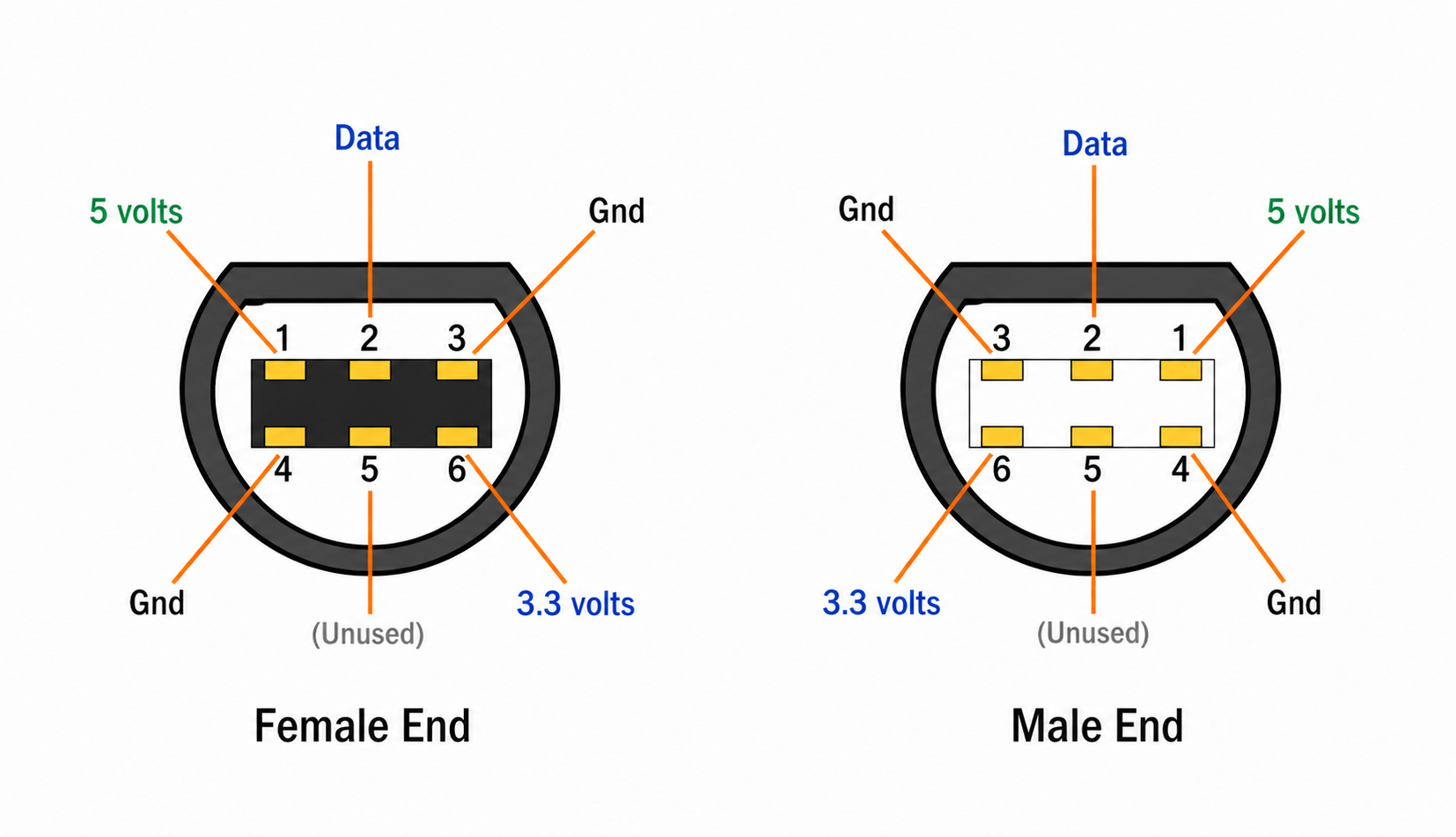
| Pin | Signal |
|---|---|
| 1 | 5V (VCC) |
| 2 | Data (bidirectional joybus line) |
| 3 | GND |
| 4 | GND |
| 5 | (unused) |
| 6 | 3.3V |
The wires come from inside the extension cable — no separate hookup wire needed. Strip back the outer jacket, then strip about an inch (~25mm) off each wire you need so it's easy to solder to the board.
Check your wiring: GameCube extension-cable wire colors vary by manufacturer — there is no reliable color standard. Use a multimeter in continuity mode to trace every wire back to its pin on the plug before soldering.
Step 2: Wire the GameCube Connection
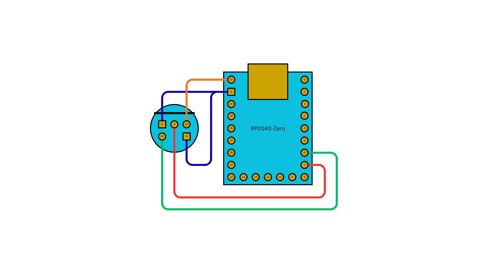
Wire the four signals you need from the GC plug to the board. Pin 5 is unused — leave it disconnected.
| GC Pin | Signal | Board Pin | Notes |
|---|---|---|---|
| Pin 1 | 5V (VCC) | 5V input (RAW on KB2040 / VBUS on Pico / 5V on RP2040-Zero) | Powers the board from the console |
| Pin 2 | Data | GPIO 7 | Bidirectional joybus data line |
| Pin 3 | GND | GND | Tie both GC grounds to the board's GND |
| Pin 4 | GND | GND | |
| Pin 6 | 3.3V | GPIO 6 | Console-presence sense line |
How presence sensing works: GPIO 6 reads the console's 3.3V line. When it detects 3.3V, the adapter knows it's plugged into a GameCube and runs in play mode. When no console 3.3V is present (i.e. powered over USB only), the adapter instead boots as a USB device for web configuration at config.joypad.ai.
The data line uses the GameCube's single-wire joybus protocol, implemented via PIO on the RP2040. The firmware handles all the timing — you just need the wire on GPIO 7.
⚠️ Safety: Do NOT power from the console and USB at the same time
The GC cable's 5V wire (Pin 1) connects to the board's 5V rail — the same rail as the board's own USB VBUS, joined through the board's protection diode. Plugging the adapter into a console and a computer's USB port at the same time ties two 5V supplies together. This can backfeed one supply into the other and stress the regulators on either side.
Use the console for play mode, OR USB for config mode — never both at once.
Reference Builds
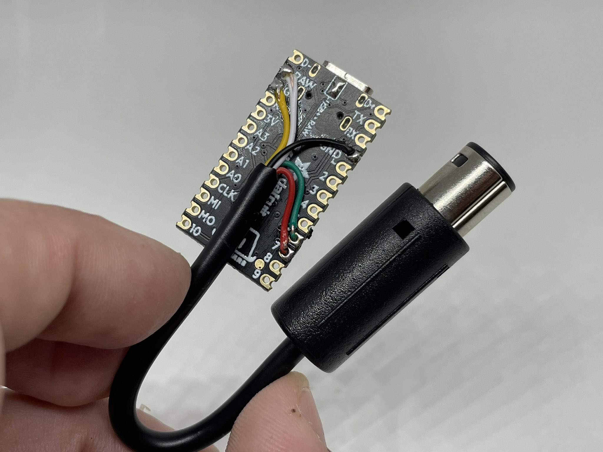
A finished KB2040 build with the GameCube cable soldered to RAW (5V), GPIO 6 (3.3V sense), GPIO 7 (data), and the GND pads:
The same wiring on a Waveshare RP2040-Zero — only the physical pad locations differ; the GC pin assignments are identical:
Step 3: Connect the USB Controller
There's no USB host port to build. The board's native USB port is the host — you plug your USB controller straight into it through a USB-A female adapter (see the Parts List for which adapter each board needs). The joybus PIO program and PIO-USB can't share the RP2040's PIO hardware, so this build deliberately reserves PIO for the GameCube data line and uses the board's built-in USB port for the controller.
KB2040 only — bridge the USB host power jumper: On the KB2040, bridge the USB power solder pads so attached controllers get full bus power. Without the bridge, controllers may not enumerate or may fail to run rumble. The Pi Pico and RP2040-Zero have this routed by default and need no jumper.
For Bluetooth controllers, none of these boards have an onboard radio — plug a compatible USB Bluetooth dongle into the host port instead.
Step 4: Flash the Firmware
Build from source
# KB2040 (also the target for the Raspberry Pi Pico)
make usb2gc_kb2040

# RP2040-Zero
make usb2gc_rp2040zero
Or download a prebuilt UF2
Go to github.com/joypad-ai/joypad-os/releases and download:
| Board | Firmware File |
|---|---|
| KB2040 / Pi Pico | joypad_*_usb2gc_kb2040.uf2 |
| RP2040-Zero | joypad_*_usb2gc_rp2040zero.uf2 |
Flash it
- Disconnect the board from everything
- Hold BOOT / BOOTSEL
- While holding, plug the USB cable into your computer
- Release the button — the
RPI-RP2drive appears - Drag and drop the
.uf2file onto theRPI-RP2drive - The drive auto-ejects — firmware is flashed
Step 5: Test It
Config Mode Test (Without a Console)
When powered over USB only (no console 3.3V on GPIO 6), the adapter boots as a USB device for configuration:
- Plug the adapter into your PC via its USB cable
- Plug a USB controller into the adapter's USB-A adapter
- Open config.joypad.ai in Chrome
- You should see the controller in the input monitor
- Press buttons and verify they register
On the GameCube
- Power off the GameCube
- Plug the adapter into a controller port (the GameCube cable end)
- Plug a USB controller into the adapter's USB-A adapter
- Power on the GameCube
- Navigate menus and test in a game
Remember the safety warning: don't leave the adapter connected to your PC's USB while it's plugged into the console.
LED Status
- 🟣 Solid purple = one controller connected and working (on boards with a NeoPixel — the Pi Pico has none, so it shows status via flash only)
Using Profiles
USB2GC has several built-in button mapping profiles optimized for different games.
How to Switch
- Hold Select for 2 seconds
- Press D-Pad Up to cycle forward, D-Pad Down to cycle backward
- Controller rumbles and LED flashes to confirm
- Profile saves to flash — it persists across power cycles
Profile Overview
| Profile | Best For | Key Differences |
|---|---|---|
| Default | Most games | Standard mapping — A/B/X/Y, analog triggers |
| SNES | SNES-style games | L/R as full digital press, Select→Z |
| SSBM | Super Smash Bros. Melee | Light shield, multiple jump buttons, tuned stick sensitivity |
| MKWii | Mario Kart Wii | Wheelie / drift / item mappings |
| Fighting | Fighting games | Right stick disabled (prevents accidental input) |
Default Button Mapping
| Your Controller | GameCube |
|---|---|
| Cross / A (B1) | B |
| Circle / B (B2) | A |
| Square / X (B3) | Y |
| Triangle / Y (B4) | X |
| RB / R1 | Z |
| LT / L2 | L (analog) |
| RT / R2 | R (analog) |
| Start | Start |
| Left Stick | Control Stick |
| Right Stick | C-Stick |
Troubleshooting
GameCube Doesn't Detect the Adapter
- Check the data line on GPIO 7 — this is the most common wiring issue
- Make sure Pin 1 (5V) and both grounds (Pin 3 and Pin 4) are connected
- Verify the 3.3V presence-sense wire (Pin 6 → GPIO 6) — without it the adapter won't enter play mode
- Re-check every GC wire with a multimeter (colors are not standardized)
- Try a different controller port on the GameCube
USB Controller Not Detected
- On a KB2040, confirm the USB host power jumper is bridged — without it, controllers may not enumerate
- Try a different controller
- Check the controller compatibility list
Rumble Not Working
- Not all controllers support rumble feedback — Xbox and PlayStation controllers do
- On a KB2040, make sure the USB host power jumper is bridged (rumble draws extra current)
Buttons Feel Wrong
- You might be on the wrong profile. Hold Select, then use D-Pad Up/Down to cycle
- The default profile maps Cross→B and Circle→A (not the other way around) — this matches GameCube layout conventions
RPI-RP2 Drive Doesn't Appear
- Hold BOOT / BOOTSEL before connecting USB
- Try a different cable (data-capable)
- Try a different USB port
What's Next?
- GC2USB Guide — Go the other direction — use a GameCube controller on PC
- USB2USB Guide — Simpler build if you just need USB-to-USB
- BT2N64 Guide — Bluetooth controllers on N64
- Controller Archive — Full compatibility list
- Community Discord — Share your build, get help
Estimated build time: 30–60 minutes (includes soldering). Difficulty: Medium.